Citrix Provisioning Services
Citrix Provisioning Services tutorials and general information on the product around system requirements, installation and configuration.
PVS install guide here.
BDM guide including automatic BDM updates in PVS 7.9+ here.
NetScaler TFTP load balancing guide here.
Streamed VM setup wizard here.
XenDesktop Setup Wizard here.
Disable Large Send Offload and other PVS recommendations listed here.
New in PVS 7.7:
Support for Windows 10 Enterprise and Professional editions.
In-place upgrade of target device software. No more having to reverse image. To upgrade target devices that have software version 7.6, first install 7.6.1 then you can perform an upgrade to 7.7+.
Support for UEFI pre-boot environments. Allowing for faster startups as you can now use gigabit network speeds.
PVS licensing grace period changed from 96 hours to 30 days to bring in-line with XenApp and XenDesktop.
vGPU XenDesktop machines can be provisioned using PVS XenDesktop Setup Wizard. Prior to 7.7 you could only use PVS STreamed VM Setup Wizard.
Generation 2 VMs (Hyper-V) can be provisioned through PVS.
VHDX streaming now available along with usual VHD streaming.
New FIPS compliant algorithm used in PVS.
New in PVS 7.8:
Support for Hyper-V Generation 2 VMs in PVS 7.8. (Streamed VM Setup Wizard does not support Gen 2 templates). You muse use the XenDesktop Setup Wizard to create VMs from a Gen 2 template.
UEFI enhancements. (BDM does not spport UEFI, only TFTP/PXE).
New in PVS 7.9:
Opt in or out of the CEIP (Customer Experience Improvement Program). 7 days to disable CEIP after installation.
BDM support for UEFI in PVS 7.9 using integration with XenDesktop Setup Wizard (attaches BDM ISO to desktop upon provisioning – eliminating extra step).
BDM creation wizard allows you to specify that target devices use UEFI firmware.
BDM partitions can be automatically upgraded by collection, single device or multiple device selection. Useful if PVS IP changes and you need to edit bootstrap to reflect change.
No need for TFTP/PXE anymore when using BDM.
New in PVS 7.11:
Always on tracing using CDF Monitor to upload diagnostic data to Citrix.
SQL Server Always On multi-subnet failover using an ODBC connection between the PVS server and SQL database. Requires SQL Native Client on PVS server.
Support for CIS in PVS 7.11 allowing you to report problems to Citrix that you experience whilst using PVS. This feature and CEIP is used by Citrix to continually improve PVS.
Windows Server 2016 support, install PVS on Server 2016 or run Server 2016 Target Device VMs.
New in PVS 7.12
Linux VDA streaming in PVS 7.12 (technical preview at this stage).
Cached secrets cleanup, removing cached admin credentials from a vDisk when private/maintenance mode is changed to shared (standard image mode).
New in PVS 7.13
Linux CentOS VDA streaming in PVS 7.13.
PVS Accelerator (XenServer) – A PVS proxy resides in XenServer’s Dom0. Streaming of the a vDisk is cached in the PVS proxy before being forwarded to a Target Device. All further booting or IO requests of the Target Device on the same host is streamed from the proxy rather than over the network from PVS. This results in reduced network traffic. PVS Accelerator works on XenServer 7.1 hosts with the required proxy feature installed. Target Devices access data directly from XenServer memory and storage instead of PVS server RAM.
New in PVS 7.14
Linux streaming improvements including support for Ubuntu Desktop 16.04.
Support for provisioning to Nutanix AHV – Using the XenDesktop Setup Wizard, you can now provision VMs to Nutanix AHV.
Microsoft Device Guard integration.
New in PVS 7.15
Expanded platform support for Linux Streaming on Ubuntu Desktop 16.04. Now support provisioning to Nutanix AHV 5.1+.
UEFI – XenDesktop supports UEFI hardware technology on Hyper-V VM that are managed using SCVMM and streamed using PVS. UEFI provides faster Target Device startup times using GB network speeds. UEFI is the complete replacement for BIOS and requires a new PVS bootstrap. Two new bootstraps are available, one for x32 systems and one for x64. BDM is not available for UEFI devices unless using PVS 7.9+. In PVS 7.7, the boot menu is not available for manual selection. If a maintenance version is detected then a target device will boot in to the maintenance mode version, the highest test version, or the production version in that order. Note this is dependant on what mode the target device is set to. The boot menu does appear to be present using PVS 7.11. I cannot speak for PVS 7.8 or PVS 7.9. If multiple vDisks are assigned to a target device the machine boots to the first one in the list. Secure Boot (Hyper-V) does not work for PVS when using easlier versions of XenApp 7.12 and must be disabled on UEFI VMs. The Secure Boot term has been replaced by Protect SDB in PVS 7.12+.
Note: You must use the most recent version of Citrix License server to get the latest features. The required version to work with your version of PVS is normally available with the PVS product software. Failing to run the latest version results in PVS entering grace period. Latest version 11.14.0.1 build 19005 (Feb 23, 2017).
PVS 7.15 server system requirements:
SQL 2008 SP3 through to SQL 2016 (x86, x64 & Express editions). Database clustering supported.
Windows Server 2016.
Windows Server 2008 R2, 2008 R2 SP1 Standard, Enterprise & Datacentre.
Windwos Server 2012, 2012 R2 Standard, Essentials & Datacentre.
Intel or AMD x64 2GHz minimum, 3GHz preferred. 3.5GHz dual-core/HT or similar when streaming to 250 target devices or more.
2GB RAM minimum, 4GB preferred. 4GB required when you have 250 vDisks or more.
100MB ethernet NIC minimum, 1GB preferred. Dual 1GB NICs when streaming to 250 target devices or more.
.NET 4.5.2 & PowerShell 3.0.
PVS 7.15 firewall requirements:
UDP 6890-6909 – Provisioning server to server communication using the Messaging Manager.
UDP 6910-6930 – vDisk streaming between Target Device and PVS Server. UDP 6910 is used as login when a device is booting.
UDP 6901, 6902, 6905 – Target device to PVS server traffic.
TCP 54321-54323 – SOAP Server communication when accessing the PVS Console.
UDP 69 – TFTP communication inbound to PVS server.
UDP 6969 – TSB communication inbound to PVS server. For BDM boot.
PVS 7.15 Target Device software supported Operating Systems:
Windows 7 SP1 Professional, Enterprise, Ultimate (Private mode only). x32/x64 editions.
Windows 8 all editions. x32/x64.
Windows 8.1 all editions. x32/x64.
Windows 10 all editions. x32/x64.
Windows Server 2016.
Windows Server 2012 & 2012 R2 Essential, Standard & Datacentre.
Windows Server 2008 R2 & R2 SP1 Standard, Enterprise & Datacentre.
RedHat Enterprise Linux 7.2, CentOS 7.2
Generation 2 (Hyper-V) VMs are supported is Server 2016, Server 2012 and Server 2012 R2 Standard, Essential and Datacentre.
PVS 7.15 Target Device software requirements:
.NET 4.5.2.
PVS 7.15 console system requirements:
1GHz CPU, 2GHz preferred.
1GB RAM, 2GB preferred.
500MB disk space free.
Windows Server 2008 R2, 2008 R2 SP1 Standard, Enterprise & Datacentre.
Windows Server 2012 Essential, Standard and Datacentre.
Windows Server 2012 R2 Essential, Standard and Datacentre.
Windows Server 2016.
Windows Vista Business, Enterprise and Ultimate.
Windows 7 & 8 all editions. x32/x64.
Windows 8.1 all editions. x64.
Windows 10.
MMC 3.O, .NET 4.5.2 & PowerShell 3.0.
PowerShell 3.0 if using PVS with SCVMM.
Hypervisor considerations (XenServer 5.6+):
MAC address on template cannot be 00-00-00-00-00-00-00.
Hypervisor considerations (SCVMM 2012+):
To stream from Synthetic NIC (after vDisk boot) on Generation 1 VMs see here.
When creating VMM VM template, choose None – customization not required when asked to configure Guest OS.
Make sure the PXE boot NIC is first in the hardware settings list.
Hypervisor considerations (ESX 4.1+):
ESX 4.x = E1000, ESX 5.x+ = VMXNET3 (supported NICs).
Enable Interupt Safe Mode on the PVS bootstrap to prevent target device displaying a partial MAC address during reboot on ESX 5.0 only.
Make sure the PXE boot NIC is first in the hardware settings list. Also be aware that the BIOS may store the NICs in a different order.
Make sure the tenplate VM and master VM have the exact same guest OS, configuration, and virtual machine version.
When creating a new VM template in ESXi 5.5 make sure that the template’s CD/DVD drive is attached to an IDE controller and not a SATA controller. This will ensure the template is compatible with the XenDesktop setup wizard.
Hypervisor considerations (Nutanix Acropolis)
You can provosion Target Device’s to AHV using the XenDesktop Setup Wizard starting PVS 7.14.
PVS spanning multiple datacentres
Lantency between PVS servers and the SQL database is important. Make sure proper testing is performed if latency is >15ms. It may be better to create a PVS farm per datacentre with a local SQL server in each datacentre. This will provide the best performance and reduce the risk of failure or sluggish perfomance. This is also how most enterprise customers implement PVS.
Latency between VDA and PVS server is important to ensure streaming is not affected. PVS servers should generally be within the same location as each Target Device.
Components of PVS:
License Server – Use existing License Server if available. Make sure the License Server is running the latest version software. You must use the latest license server when upgrading to the latest Citrix PVS. If licensing is not availale, PVS goes in to a 30-day grace period. When the grace period expires, all target devices are shut down.
PVS Database – Only one database per farm.
Console – Used to manage the PVS farm.
Network Services – DHCP, PXE & TFTP are used to obtain an IP address, boot server information and to deliver the bootstrap file to target device.
Farm – The top level of a PVS infrastructure. The farm contains Sites, PVS servers, stores, vDisks, target devices etc.
Stores – Stores are NTFS/ReFS locations on your network that store vDisk (VHDX – new in 7.7+), PVP, AVHD, LOK and Write Cache files etc.
Sites – One or more can exist in a farm. Sites contain servers, stores, vDisks etc. and may represent different office locations across the country.
Provisioning Servers – Used to stream vDisks to target devices. Any server with Stream Services installed is a PVS Server.
vDisk update management – Used to provide automation of vDisk updates. These updates can be performed on a schedule and can be used in scenarios such as Windows patching.
Device Collections – A group of target device machines are kept in a Device Collection. Generally these Device Collections contain similar functioning machine such as for example, Windows 8 Desktops.
vDisks – Contain the image file, such as Windows 8.
vDisk modes
Private image mode = Read/write access to the vDisk, streamed to a single device.
Standard image mode = Read only access to the vDisk, streamed to multiple devices.
vDisk chain – A versioned vDisk, containing the Base Image and a number of manual, maintenance or test versions.
PVS Permissions:
Different groups are available in PVS which control access and management capability:
Farm Administrator – Can manage all objects within a farm including creating new sites.
Site Administrator – Can manage all objects within a site includnig creating new Device Collections. Site Administrators cannot administer a store unless that site is set to act as the owner of the store.
Device Administrator – Can manage all objects within a device collection including assigning vDisks to a device and editing device properties.
Device Operator – Can boot, shut down, send messages to target devices and view target device properties.
Membership to each group can be configured by editing the properties of the Farm, Site or Device Collections and clicking the Security tab.
Note: The user account used to create the farm automatically becomes a farm administrator.
Database documentation:
To create a database script to pass to the SQL team, use the DbScript.exe program. This utility is located by default in C:\Program Files\Citrix\Provisioning Services. This program is present once you install the PVS Server component.
 Enable offline database support:
Offline Database Support in PVS is a feature that can be enabled to allow PVS servers to use a snapshot of the PVS database if the connection to the database is lost. The snapshot of the database is created and initialized at server startup and continually updated by the Stream Process. When the database is back online the Stream Process synchronizes any PVS server or Target Device status changes made to the snapshot back to the database.
Keep in mind that when the database is offline, the following functions are unavailable:
Auto-Add Target Devices.
vDisk updates.
vDisk creation.
Active Directory password changes.
Stream Process startup.
Image Update service.
PowerShell management functions, MCLI, Soap Server and Console management functions.
To enable offline database support, right-click Farm -> Properties.
Click Options -> Enable offline database support -> OK.

Click OK and restart the Stream Service on each server for offline database support to take effect.

Other SQL requirements:
Database sizing – The initial size of a PVS database is 20MB. The database log initial size is 10MB. A four server, load balanced PVS environment with 6 stores, 8 vDisks and 100 Target Devices can roughly have a database size of 800MB. Database sizes obviously vary based on many factors so another environment with the same capacity will likely be different.
Provisioning Services uses Windows authentication with SQL when accessing the database. SQL authentication is not supported except by the Configuration Wizard. Create a service account for database access.
Database permissions – dbcreator for creating the database and securityadmin for creating the SQL logins for Stream and SOAP services.
Additional database permissions – The Stream and SOAP accounts need db_datareader and db_datawriter permission to the database. These permissions are automatically configured when running the Configuration Wizard. These accounts must also have the following rights:
Run as service.
Registry read access.
Access to Program Files\Citrix\Provisioning Services.
Read and write access to all vDisk locations.
Note: Sometimes Windows will ask for a restart after installing the PVS Console component or Server component. Do not restart. Complete the configuration wizard before restarting the server.
Configure Bootstrap Options:
To configure bootstrap, open the PVS Console -> navigate to Servers -> right-click a server -> Configure Bootstrap.
Verbose Mode – I always recommend enabling this. Outputs system messages during the boot process for deeper insight.
Interrupt Safe Mode – Enables debugging of target device drivers that exhibit timing or boot behavior problems. (Keep disabled unless you have a problem).
Advanced Memory Support – Enabled by default to allow the bootstrap to work with newer Windows OS versions.
Network Recovery Method:
Restore network connection – When a target device loses connection with the PVS server, it will continue trying to restore the connection.
Reboot to Hard drive after x seconds – Instead of continuously trying to restore the connection, the machine will be force restarted after a defined number of seconds and booted to the local HDD.
Logon Polling Timeout – Amount of time (in milliseconds) between retries when polling for PVS servers. Each PVS server is sent a login request packet in sequence. The first PVS server that responds is used. In a non-HA setup, this value defines how often to retry the single PVS server with the initial login request. In HA environments, this value defines how quickly a target device will try the next server in a DNS round robin fashion with the initial login request.
Login General Timeout – Time in milliseconds for all login associated packets except the initial login polling time-out. This value will generally be longer than the polling time out since the target devices need time to contact all PVS servers.
The bootstrap file is important because it tells target devices which servers to connect to when booting. You can list up to four servers in the bootstrap file. This allows the target device to boot from other servers in the list if one or more is offline. Each server contains a copy of the bootstrap file which can be edited from the PVS Console. All servers should be configured with their own IP first in the bootstrap file.
Creating a Master Image:
Some PVS Master Image recommendations are listed here.
If your vDisk is going to stream to a number of different Target Devices that reside on different motherboards, network cards, video cards etc. then you must use the PVS Common Image. An example scenario would be when you stream vDisks to physical devices. Citrix provide details on creating a Common Image.
When creating a master image using the Imaging Wizard, each partition is cloned separately and must be equal or larger than the source partition regardless of how much free space is on each source partition.
Note: At the beginning of a Master Image capture using the Imaging Wizard, you may be asked to restart your machine. Ignore this prompt and let the capture complete.
vDisk assignment:
To assign a vDisk to a single Target Device, right-click the Target Device -> Properties -> vDisks -> Add.
To assign a vDisk to a Device Collection, drag and drop the vDisk on top of the Device Collection.
To unassign a vDisk from a single Target Device, right-click the Target Device -> Properties -> vDisks -> Remove.
To unassign a vDisk from multiple Target Devices, right-click the vDisk -> Unassign from Selected Device(s)… -> check devices -> Unassign.
Target Device boot process:
It is important to know that the boot process involves a Target Device contacting PVS for the bootstrap file which is delivered via TFTP. Once the bootstrap file is delivered the Target Device can boot from the assigned vDisk.
Creating views:
To create a view, right-click Views -> Create View..
Specify a name for the view and description if desired.
Click on the Members tab -> Add.
Select a Device Collection, highlight VMs to add and click OK
.
Click OK again and the devices will appear in the new view.
You can also drap and drop Target Devices on to a view, which makes them a member of that view.
Changing the PVS license server:
The License Server details are within Farm Properties -> Licensing. After changing the license server details, restart the Stream Service on each PVS Server
.
Enable auditing:
Right-click the Farm -> Properties -> Options -> Enable Auditing -> OK
.
Right-click your Site -> Audit Trail
.
Archive an audit trail:
Right-click your Farm name and select Archive Audit Trail.
Choose a location to save the .xml archive file and the end date which should be archived
.
Select or do not select Remove information archived from the Audit Trail. If you do check this box, the information archived will going forward only be viewable from the XML file.
Override stores:
Override store locations can be set individually on servers that cannot access the default store path set within the Store properties. For example:
Server 1 – Store1 – D:\PVSStore\ (retrieved from Store properties).
Server 2 – Store1 – D:\PVSStore\ (retrieved from Store properties).
Server 3 – Store1 – E:\PVSStore\ (override location).
To set an override path:
Open the PVS Server Properties -> Stores.
Select the required Store and click Edit.
Under Path used to access the store, insert the override location.

Click OK.

PVS Server Properties
What can you set here?
Power Rating (General tab) – You can assign a power rating based on 0.1-1000.0 for each PVS server. If PVS1 has a power rating of 1 and PVS2 has a power rating of 2 then PVS2 is considered twice as powerful and will be assigned twice the number of target devices. By default each server power rating is set to 1.0.
Log events to the server’s Windows Event Log (General tab) – Enabling this option will log PVS events to the Windows Event Log.
Streaming IP Addresses (Network tab) – The list of IP addresses that the PVS Stream Service should use for a target device/PVS server communication.
Ports (Network tab) – Range of UDP ports for streaming communication. By default UDP 6910-6930 are used. This allows for 160 Target Devices to stream from one PVS server.
Stores (Stores tab) – List of all stores including their path which is either default from store or an override path.
Active Directory (Options tab) – Allows you to enable which is a default the automation of computer account updates. Also allows you to specify how many days between password updates.
There are also a number of settings in Advanced Server Properties.
Threads per port (Server tab) – The number of threads in the thread pool that service UDP packets received on a given UDP port. Citrix say between four and eight is reasonable. 8 is the default setting. Setting the bar higher allows more target devices per port but consumes more system resources.
Buffers per thread (Server tab) – The number of packet buffers allocated for every thread in a thread pool. Setting this value too large consumes extra memory but does not affect efficiency. Setting the value too small on the otherhand does affect efficiency at the expense of using less RAM.
Server cache timeout (Server tab) – Every PVS server periodically writes status information to the PVS database. Every status information write is time-stamped. A server is considered online by other PVS servers in the farm if the status information in the database is newer than the cache server timeout. Every PVS server in the farm will attempt to write its status information at twice the speed of the timeout value. For example, the timeout value by default is 8 seconds so each PVS server will attempt to write its status information every 4 seconds. A shorter cache timeout value will allow servers to detect offline servers quicker at the expense of more database overhead whilst increasing this value will reduce the database load but servers will take longer to detect offline servers.
Local and Remote Concurrent I/O limits (Server tab) – Controls the number of concurrent I/O transactions that can be sent to a given storage device. A storage device is defined locally (C:\, D:\) or networked via UNC paths. Since the PVS service is a highly multi-threaded service it is possible for it to send hundreds of simultaneous I/O requests to a given storage device. These requests are then usually queued up by the storage device and processed when time permits. Some storage devices (Windows Shares notable) do not cope well with a large number of concurrent requests. As a result connections can be dropped or long times are taken to process transactions. By throttling the I/O transactions in the PVS service, better performance can be achieved. If you have a slow machine providing a network share, or slow drives on the machine, a count of 1 to 3 for the remote limit may be necessary to achieve best performance with the share. If you have fast local drives you may be able to set the local count fairly high. For the optimal setting, you will need to test. Setting either count to 0 disables the feature and allows the PVS service to run without limits. This might be desirable on very fast local drives. By default the remote and local I/O limits are set to 4. If a network share is overloaded, you’ll see a lot more device retries and reconnections during boot storms etc. This is caused by read/write and open file times. Throttling the concurrent I/O transactions on the share reduces these types of problems considerably.
Ethernet maximum transmission unit (MTU) (bytes) (Network tab) – The number of bytes that fit in a single UDP packet. For standard ethernet, the default value of 1506 bytes is correct. If you are attempting to operate over a WAN a smaller value may be needed to prevent IP fragmentation. PVS does not support IP fragmentation and reassembly. If you are using a device or software layer that adds bytes to every packet, a smaller value may be needed to compensate. If your entire infrastructure (PVS NIC, Target Device NIC, Switches and Routers in between) support jumbo packets then you can set the MTU to 50 bytes less than your jumbo packet max size to achieve much higher network throughput.
I/O burst size (KB) (Network tab) – The number of K bytes that will be transmitted in a single read/write transaction before an ACK is sent from the server or device. The larger the I/O burst the faster the throughput to an individual device however more stress is places on the network and server infrastructure. Larger burst I/O also increased the risk of lost packets and costly retries. Smaller I/O bursts reduces the throughput to a client, reduces the server and network infrastructure load and the likelyhood of retries.
Boot pause (seconds) (Pacing tab) – The number of seconds a device will be told to pause if the Maximum devices booting limit has been reached. The device will continue to check with the server ever Boot pause seconds until the server allows the device to boot. By default the boot pause is 10 seconds and the boot device limit is 500 devices.
Maximum boot time (minutes:seconds) (Pacing tab) – The amount of time boot pacing will consider a device to be in the booting stage.
Maximum devices booting (Pacing tab) – The maximum number of devices a server allows to boot at any one time before pausing new booting devices. The number of booting devices must drop below this limit before the server will allow more devices to boot.
vDisk creation pacing (Milliseconds) (Pacing tab) – Amount of pacing delay to introduce when creating a vDisk on this PVS server. Larger values increase the vDisk creation time but reduce PVS server overhead to allow target devices that are running to continue running efficiently. The default vale is 0 milliseconds.
License timeout (minutes:seconds) (Device tab) – The amount of time from last hearing from a target device to hold a license before releasing it for use by another target device. If a target device for example loses power unexpectedly its license is held for this long. Licenses are checked out on boot
.
Copying server properties:
To copy PVS server properties from one server to another PVS server:
Right-click your PVS server -> Copy server properties.
Now select the properties you want to copy and click OK.

Next right-click the destination PVS server and select Paste.
Select the settings you want to paste and click Paste.
Restart the Stream Service on the destination PVS server for the new properties to take effect.
View Target Devices streaming from a PVS server:
To get a list of which Target Devices are streaming of a particular PVS server, right-click the desired PVS server. Click Show connected devices. From here you can reboot Target Devices or send a message etc.
View Target Devices using a vDisk:
Right-click desired vDisk – >Show Usage.
From the Show vDisk Usage screen you can reboot, shutdown or send a message to any of the Target Devices. You can also get information such as Device IP, Server IP, Server Port, Retries, vDisk version, vDisk Full Name and Access mode.
vDisk Load Balancing:
To enable Load Balancing on a vDisk:
Right-click your desired vDisk and select Load Balancing. Under Use the load balancing algorithm select one of the following:
Subnet Affinity – None – Ignore subnets, use least busy server. Default setting.
Subnet Affinity – Best Effort – Use the least busy server/NIC combination from within the same subnet. If no server/NIC combination is available within the subnet, select the least busy server from outside the subnet. If more than one server is available within the selected subnet, perform load balancing between those servers.
Subnet Affinity – Fixed – Use the least busy server/NIC combination from within the same subnet. Perform load balancing between servers in that subnet. If no server/NIC combination exists in the same subnet, do not boot Target Devices assignd to this vDisk.
Rebalance Enabled – This setting (percentage value) can be enabled to rebalance the vDisk should it end up being streamed from a particular server more than other PVS servers that can provide the vDisk. For example, a 20% trigger value would initiate a vDisk rebalance if a server had 20% more load compared to other PVS servers that could provide the vDisk.
Note: The load balancing algorithm takes into account the PVS power rating which is talked about above
.
Target Device Templates:
A template device can exist per Device Collection. Any newly created Target Device can inherit the template settings (apart from name and MAC) to speed up the creation process and decrease manual input. To set a Target Device as the template:
Right-click your desired Target Device -> Set Device as Template -> Yes.
You can also copy Target Device properties to paste on to other devices.
Right-click your desired Target Device -> Copy Device Properties.
Select the properties to copy and click Copy.
Right-click the destination Target Device -> Paste -> Paste.
Note: You can select and paste to multiple Target Devices from the same or different Device Collections.
Copying vDisk properties:
Right-click desired vDisk -> Copy vDisk Properties.
Choose from the list the properties you want to copy then click Cop
.
Right-click the destination vDisk -> Paste -> Paste.
Target Device Status:
The Status tab (right-click Target Device -> Properties -> Status) provides some useful information such as:
IP Address – The IP address of the Target Device.
Server – The PVS server this machine is streaming its vDisk from including PVS server IP and UDP streaming port.
Retries – The amount of retries encountered since the vDisk started streaming to this Target Device.
vDisk – The vDisk name.
vDisk version: The vDisk version number.
vDisk full name: The full vDisk name and extension.
vDisk access: Production, Maintenance or Test.
Shutting down or restarting Target Device or collection of devices:
Either right-click a single Target Device, multiple Target Devices or a Device Collection.
Point to Target Device -> Shutdown or Restart.
Enter a message for users and a value for Delay seconds which will delay the shutdown for the specified seconds.
Click Shutdown devices or Restart Devices.
BIOS-embedded bootstrap:
The BIOS embedded bootstrap feature is for machine that have the PVS bootstrap embedded in to the BIOS. This feature is OEM specific and provides users with systems preconfiugured with PVS. This feature becomes an alternative to the PXE boot method.
Target Device Status Tray:
The Status Tray (Virtual Disk Status) is a piece of software that runs on each Target Device giving information that you can use for troubleshooting or baselines etc. The following below information is presented:
Virtual Disk Information (General tab):
Status – Active or inactive (Target Device is or is not currently accessing this vDisk).
Server – The IP address of the PVS server streaming this vDisk to the Target Device and the UDP streaming port being used.
Boot From – If Target Device is set to boot from vDisk or local Hard Disk or Floppy Disk.
Virtual Disk – The vDisk name that is being streamed to this Target Device.
Mode (General tab):
vDisk – Read Only or Read and Write.
CacheType – Cache type used for example Device RAM with overflow on local hard drive.
Cache Size – Dependant on the cache drive size.
Cache Used – The cache size and percentage used.
Version (General tab) – PVS version and build.
Preferences (General Tab):
Prompt status message in System Tray – Enabled by default. Enables the Status Tray to automatically start when a user logs on to the Target Device.
Show icon in System Tray – Enabled by default. Shows the icon in the notifications tray in Windows.
Boot Statistics (Statistics tab):
Boot time – Number of seconds it took during the boot phases of the operating system. This value doesn’t include POST, BIOS, PXE, DHCP or TFTP processing times.
Retries – The number of packet retries that occured during boot phases.
Bytes Read – The number of bytes read during the boot phases.
Bytes Written – The number of bytes written during boot phases.
Throughput – A value calculating the overall throughput of the software during the boot phases. Throughput is calculated by adding the bytes read/written values then dividing that by the boot time in seconds.
Session Statistics (Statistics tab):
Uptime – The length of time this Target Device has been online.
Retries – The number of packet retries encountered.
Bytes Read – The total number of bytes read.
Bytes Written – The total number of bytes written.
Diagnostic Statistics (Statistics tab):
Uptime – The length of time the Target Device has been online.
Retries – The total number of retries.
Bytes Read – Total number of bytes read.
Bytes Written – Total number of bytes written.
Target Devices that use personal vDisks:
Personal vDisks (PvD) are created using the XenDesktop Setup Wizard (turorial at beginning of this section). These personal vDisks are made for users who use a VDI desktop with a static pooled desktop. PvD’s allow the user to personalise their desktop but still allow the administrator to stream one standard read-only vDisk for example. Personalisation is any change to the desktop such as application installs, application setting changes, document downloads etc.
Default drive letter for PvD is P: but can range from E: to Z:.
vDisk Cache Modes:
The different vDisk cache modes are:
Cache on device hard drive (deprecated 7.12+) – The cache file is stores on an NTFS drive within the Target Device. Write requests are kept within the Target Device. The WC drive should be formatted with MBR. GPT is not supported.
Cache on device hard drive persisted (deprecated 7.12+) – The same as above only the write cache file persists between reboots. This write cache mode is experimental and supported only on NT6.1 or later. This method also requires a different bootstrap (CTXBP.bin).
Cache in device RAM – Write cache can exist as a temporary file in the target devices RAM. This provides the fastest method of disk access as writing to memory is always faster than writing to disk.
Cache in device RAM with overflow on hard disk – The write cache is written to RAM first until the RAM limit is reached. After the RAM limit is reached the least recently used block of data is written to local HDD to accomodate for newer write cache data on RAM. The WC drive should be formatted with MBR. GPT is not supported.
Cache on server – The write cache is stored on a PVS server. This is a slow type of cache feature since writes from the Target Device will need to traverse the network. The cache is wiped on reboot.
Cache on server persistent – Same as above only the cache is retained during reboots. Each Target Device will have their own specific cache file which is uniquely named. Persisted cache files will be persisted if for example you create a maintenance mode version on the vDisk or change the vDisk from Standard to Private Image mode. Invalidated cache files need to be manually deleted.
Note: If you have multiple drives attached to each Target Device and the Write Cache is ending up on the wrong one, create a file called {9E9023A4-7674-41be-8D71-B6C9158313EF}.VDESK.VOL.GUID on each drive that you do not want the Write Cache to reside. For example, C:\ and E:\ have this file present, D:\ does not. This results in the Write Cache being placed on D:\.
Deleting the Write Cache from a persisted server cached vDisk:
This option is only available if the vDisk uses a cache method of Cache on server persisted.
Right-click the Cache on server persisted vDisk -> Delete cache from selected device(s).
Select from the list the devices you want to delete the cache from then click Delete.
Replicating vDisks:
PVS support the replication of vDisks that are stored on local or locally attached storage on PVS servers. I have used DFS-R numerous times with great success. Each PVS server participating in replication must have network connectivity to each other. The PVS files that should be replicated include:
VHDX, AVHDX, and PVP.
.LOK files should not be replicated.
Note: DFS-N (Namespaces) are not supported as store paths.
To view the replication status of a vDisk, right-click the desired vDisk and select Replication.
If replication has not reached one or more PVS servers an orange warning icon will appear beside the server name. Hovering over this icon will indicate why replication is not complete. This can be handy when troubleshooting replication such as when required files are missing or out of date.
Note: The PVS Stream Service account needs to have full control permissions over each vDisk.
Releasing vDisk locks:
vDisk locks occur when Target Devices boot to a vDisk. When the Target Device is gracefully shut down the lock is removed. In some cases such as unexpected power outage to the Target Device, the lock may not be released. The locks however can be released manually by an administrator.
To release a vDisk lock:
Right-click on the desired vDisk -> Manage Locks.

Click Yes on the “Ensure vDisk is not in usage” warning.
Check each Target Device you want to release then click Remove Locks.
Expanding a vDisk
Merge all vDisk versions together
Take a copy (backup) of the VHDX file
Use diskpart or GUI to expand the vDisk
Detach vDisk and import back to PVS
Importing Target Devices into a collection:
Target Devices can be imported to a Device Collection from a .csv file. The .csv file can be created with NotePad using a .txt file and then the extension renamed to .csv, or it can be created with Excel.
Each line in the .csv file should be formatted as:
DeviceName,MACAddress,SiteName,CollectionName,Description,Type
All of the properties above are easily identified. The Type field should be either:
0 for production.
1 for test.
2 for maintenance.
The MAC address can contain colons, hashes or nothing.
To access the Import Devices wizard:
Right-click a Device Collection -> Target Devce -> Import Devices.

Click Next.
Search for and select the .csv file and click Next.
Choose if you want to apply the template device properties to these imported Target Devices or not. Click Next.
The list of Target Devices to be imported appear. Click Finish.
Managing domain account passwords
When Target Devices boot from a standard mode vDisk, the PVS server assigns the target device its name. In a domain environment, this PVS Target Device name and the password must match the information in the corresponding computer account that exists in Active Directory. If it does not, the Target Device is not able to log on successfully. To achieve name and password compliance the PVS server must manage the domain passwords for Target Devices that share a vDisk.
To allow the PVS to manage passwords, you must disable the Active Directory controlled machine password changes. This can be done via GPO with the setting Domain Member: Disable machine account password changes which is found in Computer Configuration -> Policies -> Windows Settings -> Security Settings -> Local Policies/Security Options. This policy should be applied to the OU that contains your Target Devices.
To confgure computer account password updates from PVS
Enter the properties of each PVS server.
Click the Options tab.
You can now control the number of days between password updates and it passwords should be updated automatically (default).
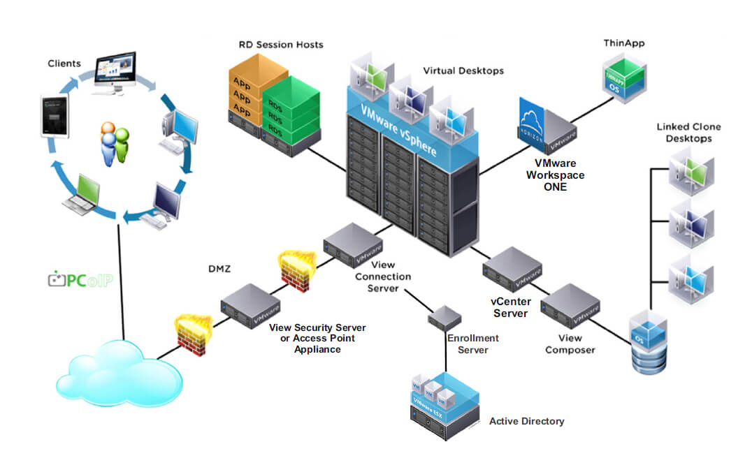
 Horizon View Connection server or connection broker or some time we call it as view manager, its a central component of VMware Horizon View infrastructure. View connection server server is running on top windows server operating system, as of now there is no appliance is available for connection server. Single connection server can handle 2000 sessions at a time (Recommended from VMware). Its primary role is to connect a user to their virtual desktop by means of performing user authentication, and then delivering the appropriate desktop resources based on the user’s profile and user entitlement.


